
 This device is used to photograph moving objects by triggering a camera
or flashgun when one or two light beams are interrupted. It was designed
to capture insects in flight, but can also be used for projectiles and
anything else that moves too fast or irregularly to be photographed by hand.
It cost around $30 to build, and was used to make The Barista Collection.
This device is used to photograph moving objects by triggering a camera
or flashgun when one or two light beams are interrupted. It was designed
to capture insects in flight, but can also be used for projectiles and
anything else that moves too fast or irregularly to be photographed by hand.
It cost around $30 to build, and was used to make The Barista Collection.
For a simpler, cheaper device, see CamTrigJunior.
For a much better device using a microprocessor, see CamTrigPro.
And now (2015) I have an even better version, which is both cheap, easy to make and sophisticated, based on the Arduino processor. I hope to have instructions for the CamTrigProPlus soon.
Meanwhile, you can easily modify this sound trigger.
There are several commercial triggers available (a good example is The Time Machine), but they all have a single beam that fires the camera when interupted, anywhere along its length, whereas this device has the option of having a second beam perpendicular to the first, so that the triggering area is much smaller, resulting in fewer out-of-frame subjects. Plus it's a lot cheaper, and can be modified to perform more specialised tasks.
And now we have the TriggerTrap, which uses all the smarts of your smart phone to trigger your camera or flash. Not so good for laser interruption, but many other cool functions, including sound and subject movement triggers.
For details of Nikon D70/D80 issues, see : http://xray.bmc.uu.se/markh/cam_trig/d70_trigger.html.
If you have trouble finding the IPL530 (DAL), try these guys http://www.gsi.uk.com, or replace that part of the circuit with a phototransistor as used in CamTrigJunior.
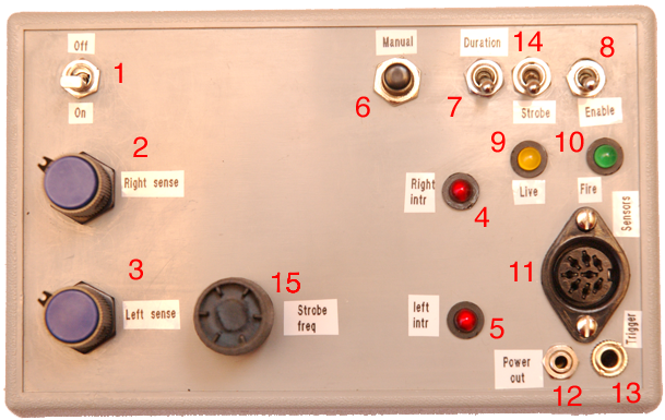
Now adjust the sensitivity of sensor A (2) so that with the beam
uninterrupted, the red trigger-confirmation LED (4) is just illuminated.
Interrupting the beam should then make the LED go out. If it does not,
turn the dial anti-clockwise a little more, whilst still keeping the LED lit.
If the LED does not light regardless of the position of the dial, a brighter
(or better aimed) light source should be used.
Once adjusted, decide whether
you want to use a second, intersecting beam. If not, turn the sensitivity
control for sensor B (3) fully anti-clockwise, so that it detects no light
and behaves as though it is always interrupted.
If you do want a second beam,
set it up perpendicular to and intersecting the first, in such a way that
when your subject interrupts both beams simultaneously, it is centered
in the camera viewfinder and in the plane of focus. Adjust the sensitivity
control for sensor B (3) in the same way as you did for A.
Now when both beams are interrupted at the same time, you will see the
yellow trigger-confirmation LED light briefly. If the output-enable switch (8)
is down, the green output-confirmation LED (10) will also light.
Now you can plug your camera or flash into socket 13. The flash cable should
fire any flashgun in manual mode, or one with a built-in automatic exposure sensor on the flash.
TTL flash operations will not work. To use the flash mode, the camera shutter
must be left open in total darkness while waiting for the trigger. This
means either very dark surroundings (such as a bat cave), or expectation of
fairly rapid triggering (such as a box containing a flying insect).
To fire a camera it must have a
connection which needs to be short-circuited to fire the shutter. I use
the 2.5mm socket on the motordrive of my Olympus OM-4, and would hesitate
to plug it in to any other camera without checking the technical specifications.
To trigger the Nikon D70 you will need to make a switch to connect to the
remote control (ML-L3), such as described here,
and will need to switch on the strobe function with the strobe frequency
knob dialed fully clockwise, so that the camera is triggered every 13 minutes
regardless of beam interruption, thus ensuring that the reomte-control
function on the camera does not time-out.
The strobe function can also be used to make time-lapse sequences, with intervals down to a few seconds.
There is also a delay control (not yet shown in the picture of the box), which is enabled with switch (16) and adjusted with dials (17). This allows for a delay of up to 100 mS, if you don't want to catch the activity exactly when the beam is broken.
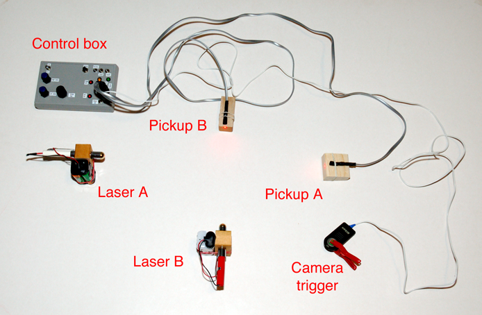
The purpose of the pulse-duration swith (7) is to allow for the different characteristics of different pieces of equipment. The longer output pulse (around 1 second) is suitable for motordrives that have insensitive triggers and which may miss a shorter pulse, whereas the shorter pulse (10ms) prevents multiple firing of some flashguns that are confused by longer pulses. The intermediate position (100ms) prevents strobing from, for example, insect wing beat in the beams, whilst still keeping most flashguns happy. The following pictures may or may not make things clearer. In the first picture the apparatus is laid out on a tabel for clarity and is not a functional arrangement, but the second is a setup for photographing butterflies in the wild.
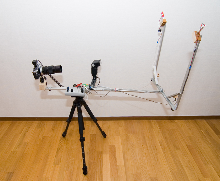
A functional arrangement set up in order to photograph small flies
can be seen here, and to photograph
splashes in a coffee cup here.
The insect is captured in the detachable film canister, which is then coupled
to the transparent tube with the beam detectors attached. The beam was collimated
down to less than 1mm with a thin plastic tube for this application.
Incidentally, to get the close-ups I use a 150mm lens on the camera
with a 50mm lens reversed on the front of the tele. Filter-to-filter
threaded rings are available to attach lenses like this, but sticky tape
works fine too. Magnification increases with decreasing focal length
of the reversed lens, but I use the 50mm because it is the fastest lens
I have, and a slow reversed lens causes more vignetting.
With the extension tubes added, I get a field of 8mm at 35mm focal distance.
© Mark Harris 2008, but feel free to distribute without changes.