DIY High-speed LED flashgun
Frozentime Images Photography (frozentime.se) and Uppsala University
|
Professional still-image cameras usually have a top shutter speed of around 1/10 000 s or 100 microseconds. To study events happening faster than this, electronic flash is normally used.
Light-emitting diodes on the other hand, can be switched on and off in less than 1 us, but cannot emit light of great intensity without fatally overheating.
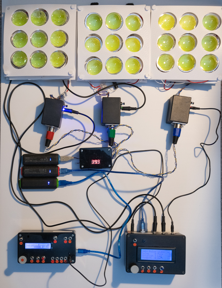
With all this in mind, we have constructed an array of 27 cheap 100W LEDs from ebay along with associated control electronics that can be used for high-speed imaging down to approximately 5 us. Although we can supply 50 amp pulses for as short as 1us, when we monitor with a photodiode, we see a slow exponential decay over several microseconds, which is probably due to the phosphors on the LEDS, but we haven't ruled out this being an artifact from a slow responding photodiode. 50 amps x 60v for each 9-LED panel means each LED is disipating around 330w, 3 times what they are designed to handle continuously. The total power consumption for the 27 LEDS is around 10 KW, or around 0.1 Joules over 10 us, which is consistent with our observation that it gave around 3-stops lower photographic exposure compared to a 100 J flashgun fired at 1% power.
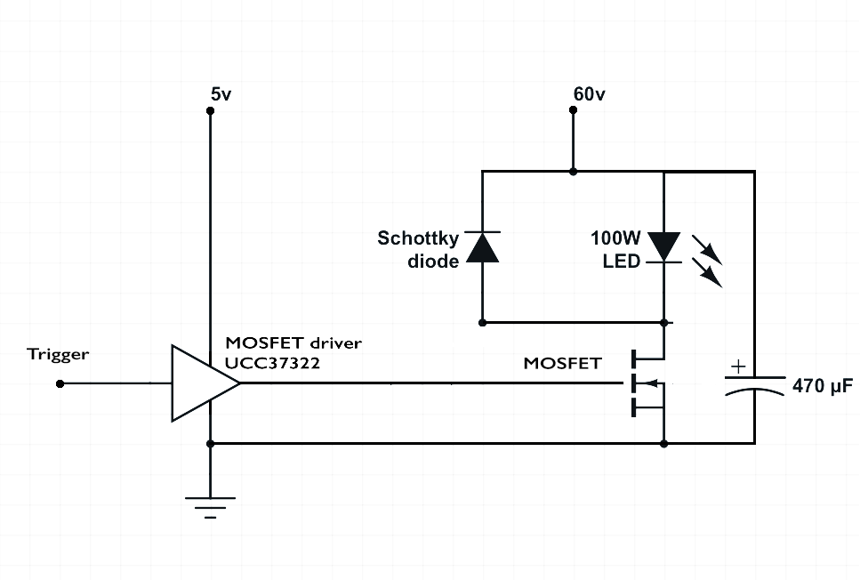
The LEDs themselves comprise a matrix of 100 individual diodes, each rated to emit 1 watt continuously, and each 100W array is covered by a lens to focus the light. The 60v supply is provided by a 5v powerbank that is fed into a simple step-up inverter,
whose display tops out at 39.9v, despite actually outputting 60v. We got lucky there - of a dozen inverters we bought, one 'accidentally' gave us the voltage we wanted, so we could avoid a more complicated power supply.
The assembled system The box on the right contains the LED drivers and can control simple operations. For more complex sequences, the box on the left allows more control, and feeds the driver box with instructions.
The image below is of a pellet ejected from a soft-air gun at 80 m/s.
|
|
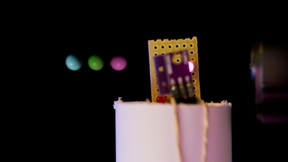
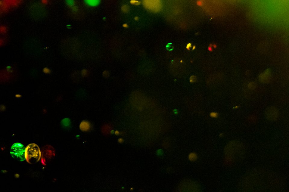
The system was built to study the size, shape, and velocity of aerosol particles emitted by fuel-injector nozzles. The image below is a preliminary image from that study. The droplets have travelled ~ 1mm during the strobe period of 10 us, indicating a speed of 100 m/s. The smallest visible droplets are ~ 10 um wide.
|
|
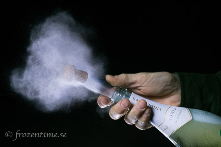
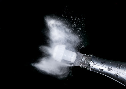
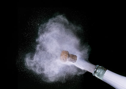
The champagne cork on the left below was shot with one of the fastest conventional electronic flashguns (Nikon SB800, ca 40 us), the one on the right with a 5us burst from a LED array. Considerable motion blur is visible with the SB800, none is discernable in the LED image.
|
© 2016 Mark Harris, frozentime.se